Contamination Analysis on PCB

Success Stories

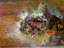
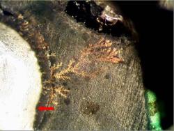
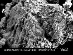
Contamination on Capacitor Sleeves, Pins, Oscillator

Contamination on Capacitor Sleeves, Pins, Oscillator

Gideon Analytical Laboratories received a Printed Circuit Board (PCB) with contamination on several capacitor sleeves, connector pins, and an oscillator. An electrolytic capacitor is a capacitor whose anode (+) consists of pure aluminum foil with an etched surface, covered with a uniformly very thin barrier layer of insulating aluminum oxide, which operates as a dielectric. The electrolyte, which covers the rough surface of the oxide layer, operates as the second electrode, the cathode (-). E-caps have the largest capacitance values per unit volume compared to the two other main conventional capacitor families, ceramic and plastic film capacitors, but much smaller capacitance than similarly sized supercapacitors. Aluminum electrolytic capacitors are divided into three subfamilies by the type of electrolyte. There are non-solid (liquid, wet) aluminum electrolytic capacitors, solid manganese dioxide aluminum electrolytic capacitors, and solid polymer aluminum electrolytic capacitors. Basic parts to an electrolytic capacitor include anode foil, a dielectric, cathode foil, cathode oxide layer, non-solid electrolyte, paper spacer, conducting polymer, among other materials. An electronic oscillator is an electronic circuit that produces a periodic, oscillating electronic signal, often a sine wave or a square wave. Oscillators convert direct current (DC) from a power supply to an alternating current (AC) signal. They are widely used in many electronic devices. The goal was to identify the contamination on the capacitor sleeves, connector pins, and an oscillator.
Contamination and Moisture on MLCCs

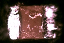
Contamination and Moisture on MLCCs

Gideon Analytical Laboratories received a printed circuit board (PCB) with suspected failing multi-layered ceramic capacitors (MLCC). Multilayer ceramic capacitors are fixed value capacitors in which ceramic the material acting as the dielectric. It is made up of two or more alternating layers of ceramic and a metal layer acting as the electrodes. There are various types of materials that could function as the dielectric in a capacitor, for example, glass, porcelain, paper, or mica. Each PCB has four suspected failing MLCCs, and the goal was to determine the cause of these failures.

Corrosion on Pcb Inside Valve

Corrosion on Pcb Inside Valve

Gideon Analytical Laboratories received two valves with failed printed circuit boards (PCBs) and corrosion inside the housing. The goal was to determine what the corrosion was and why the PCB failed. A printed circuit board mechanically supports and electrically connects electronic components using conductive trace lines, pads and other features etched from copper sheets laminated onto a non-conductive substrate. The boards are made from glass reinforced plastic with copper tracks in the place of wires. Components are fixed in position by drilling holes through the board, locating the components and then soldering them in place. The copper tracks link the components together forming a circuit. PCBs are used in all but the simplest electronic products. They are a quintessential part of the electronics industry. With decades of experience working with PCBs and advanced knowledge in electrical engineering and chemistry, this proved to be a case that was easy to solve.

Corrosion on Polyimide and Silicone PSA

Corrosion on Polyimide and Silicone PSA

Gideon Analytical Laboratories received a flex circuit with a mystery corrosion on the polyimide and silicone pressure sensitive adhesive (PSA). There was corrosion by-product, and the silicone adhesive appeared more like a gelatinous material than a tactic PSA. Contrary to popular belief, flex circuits are not training for a future bodybuilding competition, they are a technology for assembling electronic circuits by mounting electronic devices on flexible plastic substrates, such as polyimide, PEEK or transparent conductive polyester film. Additionally, flex circuits can be screen printed silver circuits on polyester. Flexible electronic assemblies may be manufactured using identical components used for rigid printed circuit boards, allowing the board to conform to the desired shape, or to flex during its use. A polyimide is a polymer of imide monomers, and have been in mass production since 1955 due to their diverse applications. The goal was to figure out what the mysterious corrosive substance on the polyimide and silicone PSA on the flex circuit was.

Problems with Track Lighting

Problems with Track Lighting

Gideon Analytical Laboratories received several lighting tracks for failure analysis. They all had what appeared to be arcing which caused severe copper pitting, melting of the Noryl, and distortion of the power bus bar. The neutral bus was also pitted but not nearly as bad as the power rail. Electrical arcing is an electrical breakdown of a gas that produces an ongoing electrical discharge. The current through a normally non-conductive medium such as air produces a plasma; the plasma may produce visible light. An arc discharge is characterized by a lower voltage than a glow discharge, and it relies on thermionic emission of electrons from the electrodes supporting the arc. An arc between two electrodes can be initiated by ionization and glow discharge, as the current through the electrodes is increased. The breakdown voltage of the electrode gap is a function of the pressure, the distance between electrodes and the type of gas surrounding the electrodes. When an arc starts, its terminal voltage is much less than a glow discharge, and current is higher. An arc in gases near atmospheric pressure is characterized by visible light emission, high current density, and high temperature. NORYL resins are a rare example of a homogeneous mixture of two polymers. Most polymers are incompatible with one another, so tend to produce separate phases when mixed. The two polymers compatibility in NORYL resins is due to the presence of a benzene ring in the repeat units of both chains. The goal was to determine why there was electrical arcing on these lighting tracks.

PCB with Open in PTH

PCB with Open in PTH

Gideon Analytical Laboratories received one printed circuit board (PCB) with an open in the plated through hole (PTH). A printed circuit board mechanically supports and electrically connects electronic components using conductive tracks, pads and other features etched from copper sheets laminated onto a non-conductive substrate.  Advanced PCBs may contain components - capacitors, resistors or active devices - embedded in the substrate. PCBs are used in all but the simplest electronic products. Plated through holes are a type of through-hole technology, which refers to the mounting scheme used for electronic components that involve the use of leads on the components that are inserted into holes drilled in PCBs and soldered to pads on the opposite side either by manual assembly or by the use of automated insertion mount machines. The goal was to determine whether or not contamination caused the open in the via.

Pulse Transformer 144A9111

Pulse Transformer 144A9111

Gideon Analytical Laboratories received two 144A9111 pulse transformers with the secondary wiring shorting. Transformers are devices that transfer electric energy from one circuit to another, usually with a change in voltage. Pulse transformers are transformers optimized for transmitting rectangular electrical pulses. Ideally, pulse transformer designers try to minimize voltage droop, rise time, and pulse distortion. Small versions called signal types are used in digital logic and telecommunications circuits, often for matching logic drivers to transmission lines. Medium-sized power versions are used in power-control circuits such as camera flash controllers. Larger power versions are used in the electrical power distribution industry to interface low-voltage control circuitry to the high-voltage gates of power semiconductors. Special high voltage pulse transformers are also used to generate high power pulses for radar, particle accelerators, or other high energy pulsed power applications. Of the two144A9111 pulse transformers with the secondary wiring shorting, one was completely exposing the seconding wire and the other was still intact on the printed circuit board (PCB). The goal was to determine the cause of the failure.

153D8496G1 Circuit Card Assembly

153D8496G1 Circuit Card Assembly

Gideon Analytical Laboratories received two 153D8496G1 printed circuit boards (PCBs)for failure analysis. A PCB mechanically supports and electrically connects electronic components using conductive tracks, pads, and other features etched from copper sheets laminated onto a non-conductive substrate. Some of the electronic components that might appear on a PCB include semiconductors like diodes or transistors, discharge devices, power sources, resistors, and capacitors. The153D8496G1 circuit card assembly has 6 capacitors, 20 resistors, and 18 semiconductors all mounted to a printed wiring board. The capacitors on both153D8496G1 PCBs were open, and as a result of the leads disintegrating in the presence of voltage and flux. The goal was to find the reason why these capacitors on the PCBs were failing.

Ion Chromatograph Analysis on Three Samples

Ion Chromatograph Analysis on Three Samples

Gideon Analytical Laboratories received three samples in polyethylene bottles to develop an analytical procedure for determining chloride using an ion chromatograph. Ion chromatography is a process that allows the separation of ions and polar molecules based on their charge. Using ion chromatography, one can identify concentrations of major anions, including elements like sodium, lithium, calcium, and many others. Aqueous samples are quantitatively measured in the parts-per-million range.

The two solutions were diluted 1:25 with DI water (18.2megaohm) water from a point of use Millipore purification system. The samples were then analyzed by ion chromatography; it was carried out with an instrument that consisted of HP1050 pump and autosampler with a Dionex AMMS suppressor and conductivity detector. Data was captured using an HP Chemstation. Displayed in the table below is the ion chromatograph readings of the respective samples. The picture shows the first sample (in red) at 3.4 PPM and the second sample (in blue) at 35.1 PPM. The results of the ion chromatography revealed the certain presence of chloride; absolute identity was made by spike, subtraction, and standards.

MOC101 Photocoupler

MOC101 Photocoupler

Gideon Analytical Laboratories received three failed Vishay MOC8101 isolating photocouplers for failure analysis. These photocouplers are components that transfer electrical signals between two isolated circuits by using light. Like the MOC8102, MOC8103, MOC8104, and MOC8105, the MOC8101 consists of a consisting of gallium arsenide infrared emitting diode optically coupled to a silicon planar phototransistor detector in a plastic plug-in DIP-6 package (http://www.vishay.com/docs/83660/moc8101.pdf) The MOC8101 were reported to have intermittent function, it was the goal of Gideon Analytical Laboratories to diagnose the cause of these failures.

Polyimide Silicone Adhesive Contamination

Polyimide Silicone Adhesive Contamination

Gideon Analytical Laboratories received a contaminated white translucent adhesive at the edge of a polyimide strip under a rubber keypad. Since most of the materials were organic, FTIR was the method of analysis first used to determine the foreign material.

The polyimide is a double-sided adhesive based flexible laminate (Kapton) film coated with adhesive on one or both and laminated to copper. There are two kinds of adhesive used in flex, epoxy, and acrylic. They each have positive and negative attributes that may make one or the other more suitable for a specific end use. The polyimide film enables the flex to bend many millions of cycles without failure. However, both acrylic and epoxy adhesives have inferior mechanical and electrical properties as compared to the Kapton core. In certain applications, the presence of an adhesive layer actually inhibits the use of flexible circuits. Therefore, a solution was needed to eliminate the adhesive layer from the substrate.

Tin Whiskers

Tin Whiskers

Gideon Analytical Laboratories performed analysis on several Melexis US2881 Sensors when the designer found shorts on the returned product from the field.

Melexis US2881 sensors are bipolar Hall-effect switches designed in mixed signal CMOS technology. They have a wide voltage operating range from 3.5V to 24V, have high magnetic sensitivity, and a chopper-stabilized amplifier stage, and are suitable for automotive or consumer applications.

Analysis revealed tin crystals (whiskers) spread throughout the top and bottom of the PCB, shorting out the MOSFET as well as the Hall sensor. Micrograph (left) and SEM-EDS analysis confirmed the presence of tin whiskers causing a short in both positive and negative leads. The tin whisker growth took place over several days to develop without voltage and with conditions known to promote growth.

Process Contamination

Process Contamination

Gideon Analytical Laboratories performed failure analysis on one opened splitter module LPF-200 PCB encapsulated in the black urethane potting material and housed in plastic. The PCB was burnt in one spot, and in that spot, a cavity existed under the carbonized epoxy of the PCB adjacent to the PTH. The trace line had a number of craters strongly suggesting an “electromigration” of copper. In order for electromigration to occur with copper a voltage, an acid and medium (moisture) must be present.

IPC-A-610 Inspection for Qualification

IPC-A-610 Inspection for Qualification

This vendor from China was in the process of qualification. There are solder dross and conductive flux underneath the conformal coating. Solder dross is highly conductive and flux will activate as an ionic conductor across leads, pads, terminals, etc.

Conformal coatings inhibit the crosstalk and ionic migration across the PCB surface. If, however, these contaminants reside on the board surface, the conformal coating cannot make contact with the solder mask and does not bond properly. This lack of bonding creates a void like space at the interface of the conformal coating and the board surface. This space is where electromigration can occur. This PCB failed many of the IPC-A-610 criteria in addition to many of the test methods used to evaluate ionic contamination.

Premature Discharge of Ansul IQ-396X Fire Circuitry

Premature Discharge of Ansul IQ-396X Fire Circuitry

Gideon Analytical Laboratories performed failure analysis on one Ansul IQ-396X, which was submitted for possible failure due to an electrical surge. These control units have two intelligent signaling line circuits (SLC), 396 intelligent device capacity (198 intelligent detectors and 198 monitors/control modules), four built-in output circuits, up to 64 internal output circuits/relays on optional modules in the unit, 99 programmable zone output relays, and manual sensitivity adjustment.

The CPU 400 unit was dissembled and the entire board and components were inspected under 40x to look for and evidence of EOS (electrical overstress) that may have affected the operation of the unit. No evidence was found. The power rails +5, +24, and ground were checked to ensure the lines were not shorted via a component failure. None were found. Continuity checks were made along the +5, +24 and the ground. No opens were found.

Tin Whisker Growth in Solder Mask

Tin Whisker Growth in Solder Mask

Gideon Analytical Laboratories received a PCB for failure analysis. The board was identified as having a short from the NET trace to the ground. The short measured about 10 ohms. One area of the board was abraded to reduce the thickness of the black solder mask. The board was received like this and we tried to change the refractive index to optically see through the solder mask. This was unsuccessful. The abraded area produces different optical characteristics, which prevent clear optical vision. Radiography did not work at all because the beam intensity attenuates and washes out any slivers traces that maybe there and works in principle by a density difference from the surrounding materials. Acoustic (sound waves, CSAM) microscopy did not work because either there are too many interfaces or the sliver may be too fine or the location is known in the material’s matrix.