Printed Circuit Board Analysis

A printed circuit board (PCB), also called a printed wiring board (PWB), holds electronic parts and connects them with copper traces, pads and plated through holes. Boards are inspected and classified to IPC standards, and Class 3 is the highest class. Each class sets limits for manufacturing defects.

PCB problems can come from the bare board or from assembly. Common failure modes include voids in plated through holes that cause opens, contamination that causes leakage or corrosion, and solder joint defects such as voiding in ball grid arrays (BGAs). Flexing during depanelization can also crack parts. Overheating and fires, and tin whiskers that cause shorts, are other cases.

The case studies in this category include a board with an open plated through hole and a board with a short caused by tin whisker growth in the solder mask. Others show BGA voiding, and flex damage to ceramic capacitors.

The lab uses X-ray radiography to look inside solder joints and vias. We use cross-sectioning with optical microscopy to check plating and layers. FTIR and scanning electron microscopy help to identify contamination.

To discuss a failed board, request a quote.

Success Stories

Browning Trail Camera Recon Force Failures

Browning Trail Camera Recon Force Failures

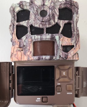
Gideon received several Browning BTC-7-4K-Edge cameras from the field. The cameras were dead on arrival. The objective was to find the cause of failure.

external photo of recon force camera

There was no external physical damage to any cameras

The batteries were replaced with new ones. The camera did not turn on; however, when it was disassembled, the full voltage resided at the solder joints of the printed circuit board.

Possible Bromine on Electrolytic Capacitors

Possible Bromine on Electrolytic Capacitors

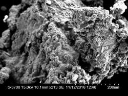
Gideon Analytical Laboratories received two power supply boards with components. The supplies were thought to have contamination, possibly bromine, causing corrosion or failing the electrolytic capacitor. The term electrolytic capacitor in a generic term for three different capacitors, which include aluminum electrolytic capacitors, tantalum electrolytic capacitors, and niobium electrolytic capacitors. All electrolytic capacitors are polarized capacitors whose anode is made of a particular metal on which an insulating oxide layer forms by anodization, acting as the dielectric of the electrolytic capacitor. Electrolytic capacitors may corrode if used or stored in a place where they encounter acidic toxic gases, like hydrogen sulfide, sulfurous acid, nitrous acid, chlorine, or bromine.

Contamination on Capacitor Sleeves, Pins, Oscillator

Contamination on Capacitor Sleeves, Pins, Oscillator

Gideon Analytical Laboratories received a Printed Circuit Board (PCB) with contamination on several capacitor sleeves, connector pins, and an oscillator. An electrolytic capacitor is a capacitor whose anode (+) consists of pure aluminum foil with an etched surface, covered with a uniformly very thin barrier layer of insulating aluminum oxide, which operates as a dielectric. The electrolyte, which covers the rough surface of the oxide layer, operates as the second electrode, the cathode (-). E-caps have the largest capacitance values per unit volume compared to the two other main conventional capacitor families, ceramic and plastic film capacitors, but much smaller capacitance than similarly sized supercapacitors. Aluminum electrolytic capacitors are divided into three subfamilies by the type of electrolyte. There are non-solid (liquid, wet) aluminum electrolytic capacitors, solid manganese dioxide aluminum electrolytic capacitors, and solid polymer aluminum electrolytic capacitors. Basic parts to an electrolytic capacitor include anode foil, a dielectric, cathode foil, cathode oxide layer, non-solid electrolyte, paper spacer, conducting polymer, among other materials. An electronic oscillator is an electronic circuit that produces a periodic, oscillating electronic signal, often a sine wave or a square wave. Oscillators convert direct current (DC) from a power supply to an alternating current (AC) signal. They are widely used in many electronic devices. The goal was to identify the contamination on the capacitor sleeves, connector pins, and an oscillator.

IXYSRF DE375-601N21A MOSFET

IXYSRF DE375-601N21A MOSFET

Gideon Analytical Laboratories received one IXYSRF DE375-501N21A MOSFET for electronic failure analysis. A MOSFET is a type of field-effect transistor (FET). It has an insulated gate, whose voltage determines the conductivity of the device. This ability to change conductivity with the amount of applied voltage can be used for amplifying or switching electronic signals. The IXYSRF DE375-601N21A MOSFET has high dv/dt, nanosecond switching, and 50 MHz maximum frequency. The IXYSRF DE375-601N21A MOSFET sent to Gideon Analytical Laboratories had a g-s short. The goal was to determine the cause of the failure.

Vishay SS26 Surface Mount Schottky Barrier Rectifiers

Vishay SS26 Surface Mount Schottky Barrier Rectifiers

Gideon Analytical Laboratories received four Vishay SS26 Surface Mount Schottky Barrier Rectifiers for possible premature conditions to failure. A Schottky barrier is a potential energy barrier for electrons formed at a metal-semiconductor junction. Schottky barriers have rectifying characteristics, suitable for use as a diode. These Vishay SS26 Surface Mount Schottky Barrier Rectifiers feature a low profile package, high surge capability, and are RoHS compliant. The diodes came from PCB P/N 170310142001 Rev A03 S/N 051208-231. Positions D8, D9, D18, and D27 were identified as possible trouble spots. The goal was to determine the cause of failure.

NEC 104PW161 Inverter Board

NEC 104PW161 Inverter Board

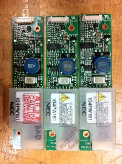
Gideon received two failed NEC 104PW161 inverter boards with Micro Fuse chip circuit protectors failing. Rather than performing a failure analysis of the fuse, the circuit was analyzed to assess the possible overuse of the fuse. This was done because the failure rate is beyond the infant mortality and before the manufacturers’ end of life prediction leading to a reliability concern over the fuse. Whether this is a true fuse issue or a design issue, this is the first step in resolving the matter.

Vishay CRCW1210-HP-e3 SM Resistor Failures

Vishay CRCW1210-HP-e3 SM Resistor Failures

Gideon Analytical Laboratories received two PCB assemblies upon which were several failing Vishay CRCW1210-HP-e3 surface mount (SM) resistors. Surface mount technology (SMT) is a method for producing electronic circuits in which the components are mounted or placed directly onto the surface of printed circuit boards (PCBs). An electronic device so made is called a surface-mount device (SMD). In the industry, it has largely replaced the through-hole technology construction method of fitting components with wire leads into holes in the circuit board. The goal was to determine the cause of the failing Vishay CRCW1210-HP-e3 SM resistors.

MH Ballast Black Box PCB

MH Ballast Black Box PCB

Gideon Analytical Laboratories received several electronic metal-halide (MH) ballast black semiconductor diode, but it also permits current to flow in the reverse direction when its “Zener voltage” is reached. The goal was to expose the circuitry and reverse engineer the cause of failure of the three components that were failing at a high rate.

Failure analysis ensued. First, the zener diodes and fuses were exposed and potting material removed so that the circuitry was revealed. After analysis of the circuitry, a notable problem stood out. The configuration had no “soft” current limiting impedance for input line spikes. Input utility power has common surges and spikes. In a regular household, this sudden inrush of electrical current exposes unprotected equipment to damaging voltages. It can overheat motors, burn out lights and damage electronic components. In order to mitigate this potential threat, a surge protector is a good idea. However, all electronics should have some inrush limiting device to prevent these input power voltage spikes from damaging equipment.

PCB with Open in PTH

PCB with Open in PTH

Gideon Analytical Laboratories received one printed circuit board (PCB) with an open in the plated through hole (PTH). A printed circuit board mechanically supports and electrically connects electronic components using conductive tracks, pads and other features etched from copper sheets laminated onto a non-conductive substrate.  Advanced PCBs may contain components - capacitors, resistors or active devices - embedded in the substrate. PCBs are used in all but the simplest electronic products. Plated through holes are a type of through-hole technology, which refers to the mounting scheme used for electronic components that involve the use of leads on the components that are inserted into holes drilled in PCBs and soldered to pads on the opposite side either by manual assembly or by the use of automated insertion mount machines. The goal was to determine whether or not contamination caused the open in the via.

153D8496G1 Circuit Card Assembly

153D8496G1 Circuit Card Assembly

Gideon Analytical Laboratories received two 153D8496G1 printed circuit boards (PCBs)for failure analysis. A PCB mechanically supports and electrically connects electronic components using conductive tracks, pads, and other features etched from copper sheets laminated onto a non-conductive substrate. Some of the electronic components that might appear on a PCB include semiconductors like diodes or transistors, discharge devices, power sources, resistors, and capacitors. The153D8496G1 circuit card assembly has 6 capacitors, 20 resistors, and 18 semiconductors all mounted to a printed wiring board. The capacitors on both153D8496G1 PCBs were open, and as a result of the leads disintegrating in the presence of voltage and flux. The goal was to find the reason why these capacitors on the PCBs were failing.

PTE43-31-C-RA Power Supplies

PTE43-31-C-RA Power Supplies

Gideon Analytical Laboratories received three PTE43-31-C-RA power supplies, two were failed and the other was a working device for comparison. Power supplies are devices that supply electrical power to an electrical load. Some power supplies convert alternating current (AC) to direct current (DC) for use in a variety of electronics. Typically, a computer needs a power supply that will convert 120 Volt AC power oscillating at 60 Hertz (Hz). Power supplies are vital to most electronic endeavors, like electrical components in machines, process automation, or for power generation. OnePTE43-31-C-RA power supply had a problem with the 5 volt (V) output line; it was going below the toleration limit of the processor and shutting down. Gideon Analytical Laboratories was determined to find the reason for this failure.

Flex Circuit Failure

Flex Circuit Failure

Gideon Analytical Laboratories received three failed Kapton based flex circuits with opens in the trace lines. The origin of the open was not known. The opens in the trace lines were traced down on the Kapton to several eyelets where contact was supposed to be made.

No areas were distinguished and no anomalies were found suggesting a trace copper foil problem on any of the circuits received. A cross-section of the above trace line and eyelet demonstrates the trace line (the line in the middle) either has been dislodged from the barrel or was never connected.

BGA Failure Analysis on Static Transfer Switch

BGA Failure Analysis on Static Transfer Switch

Gideon Analytical Laboratories received one static transfer switch (STS) Main Logic printed circuit board (PCB) assembly with two chips onboard digital signal processor (DSP)’s that were non-functional. The thought was the DSPs may have ball grid array (BGA) solder joint integrity issues causing the failures.

Analysis ensued. The three DSPs were removed from the PCB and immersed into the green dye and the DSP was pried from the main circuit board to reveal any cracked solder BGAs. The pictures below show the front and back of the DSP; there were 67 solder balls that attached to the PCB more tenaciously than to the DSP when separated. There was no cracked BGAs nor evidence of poor solder joints.

Capacitor Terminal Crack

Capacitor Terminal Crack

Gideon Analytical Laboratories received 19 multilayered ceramic capacitors (MLCCs). MLCCs have a ceramic dielectric, a ceramic or lacquered coating, a metalized electrode, and connecting terminals. Ceramic capacitors, in particular, MLCCs, are ubiquitous in all kinds of electrical equipment. Some of the MLCCs Gideon received were to test quality control, some were to test process evaluation immediately after wave solder, and some were failures in the field. The objective was to determine where these failures were entering the product and the cause of the failures.

PCB Failure Analysis

PCB Failure Analysis

Gideon Analytical Laboratories received the main PCB that had a fire in one section of the board. The objective was to find the cause in an already established product line.

This PCB had some copper deposition problems at level two copper. The deposition was seen under the diode mounted to the PCB. The deposited copper also was responsible for an internal short within the PCB. The internal short caused the electrolytic capacitor to heat up and vent toward the PCB surface onto a hot trace line. This, in turn, caused the PCB to ignite as the electrolyte caught on fire.

BGA Voiding

BGA Voiding

X-Ray Radiography Inspection

This report contains images taken of the BGAs on the two boards provided. There are no significant defects present, however, significant voiding is present throughout the two parts. The last image shows a BGA analysis performed on one of the worst areas of voiding. The analysis shows voiding greater than 15%, but less than 20%.

When run, this feature shows voiding in the solder joints as well as background features such as traces and vias, all within the same image.

PCB Overheating Due to Design Flaw

PCB Overheating Due to Design Flaw

Gideon Analytical Laboratories received several SVAA-3V25 relays for failure analysis. These solid state relays have a control voltage range between 100 VAC and 280 VAC, a load voltage rating of 330 V, and a load current rating of 25 A. Solid state relays are ideal for industrial and commercial ovens, injection molding machines, and induction furnaces, and many other applications. The goal was to find the cause of the failures.

Fire on Multilayer PCB

Fire on Multilayer PCB

Gideon Analytical Laboratories received a PCB that had a fire in one section of the board. These PCBs can provide high-performance 10G visibility for network monitoring tools in all parts of a fiber network. They feature to 24 SFP+ ports supporting 10G and 1G Ethernet (10GbE and 1GbE) and up to four RJ-45 copper Ethernet ports. The objective was to find the cause of the fire on the board, in an already established product line.

Environmental Contamination of PCBs

Environmental Contamination of PCBs

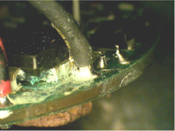
Gideon Analytical Laboratories received three central air conditioner hubs. These air conditioners can are built for commercial or residential use. Depending on their SEER ratings, they run between 66dB and 72dB and use Puron refrigerant. The hubs had corrosion on the PCB and had the appearance that some liquid flowing between the insulation and wire leading into the cavity. The goal was to discover the identity and cause of the corrosion.

Manufacturing Failure

Manufacturing Failure

Gideon Analytical Laboratories received several PCB that opened up on several of the I/O metal dome pads.

The three black circles are the time, status, and menu pads. The metal domes came out when the two switches were separated. These buttons are connected to an output. The insulator cavity (the black spots) provides space for the metal dome. The metal dome makes contact when pushed from the top switch circuitry to the bottom switch shown later. The arrows point to conductor lost from switch 2 when the two switches were separated physically. The top arrow caused an open in the bottom circuit (shown by the arrow in the next picture).

Process Contamination

Process Contamination

Gideon Analytical Laboratories performed failure analysis on one opened splitter module LPF-200 PCB encapsulated in the black urethane potting material and housed in plastic. The PCB was burnt in one spot, and in that spot, a cavity existed under the carbonized epoxy of the PCB adjacent to the PTH. The trace line had a number of craters strongly suggesting an “electromigration” of copper. In order for electromigration to occur with copper a voltage, an acid and medium (moisture) must be present.

Printed Circuit Board Flexing During Depanelization

Printed Circuit Board Flexing During Depanelization

Gideon Analytical Laboratories received two printed circuit boards (PCB) with the questionable failure of multilayer ceramic capacitors in the C4 position. Both these capacitors were removed from the PCB and the PCB was inspected for contamination for possible leakage current or electromigration that would account for conduction across the pad lands.

The picture at the top left is the C4. During analysis, no contamination was found on either of the PCBs or on any of the four sides of each capacitor. No visible mechanical marks and there were no discernible cracks. Both these caps were tested at 90% RH and 1V bias for 24 hours and resulted in excessive leakage current (measured with IR meter) within the cap. This indicates the capacitors have a leakage path internal to the structure.

Solder Joint Strain Failures

Solder Joint Strain Failures

Gideon Analytical Laboratories performed failure analysis on two printed circuit board assemblies (PCB) with fractured solder joints on the Hall Sensor interconnect. The assemblies were taken apart and the conformal coating was removed to reveal the solder joints of the Hall Sensor. Five out of six of the Hall Sensors were mounted flush against the Valox 457 mounting block.

A Hall Effect Device detects magnetic flux density and is used in both movement and position sensing. By integrating the sensing element onto the same silicon as its control logic and interface circuitry, Melexis, a maker of Hall Sensors has produced sensor chips with different degrees of intelligence to suit a vast array of applications, a pioneer in linear, programmable Hall Effect sensors, accurate rotary,and linear position indication. Incorporating memory and simple hood, safety,and drive-by-wire applications. Whether sensing actuator, pedal, throttle and steering wheel position, the rotation of camshafts or crankshafts in an engine or monitoring movement in motors, Hall devices offer a reliable, contactless method of movement and position detection.

Premature Discharge of Ansul IQ-396X Fire Circuitry

Premature Discharge of Ansul IQ-396X Fire Circuitry

Gideon Analytical Laboratories performed failure analysis on one Ansul IQ-396X, which was submitted for possible failure due to an electrical surge. These control units have two intelligent signaling line circuits (SLC), 396 intelligent device capacity (198 intelligent detectors and 198 monitors/control modules), four built-in output circuits, up to 64 internal output circuits/relays on optional modules in the unit, 99 programmable zone output relays, and manual sensitivity adjustment.

The CPU 400 unit was dissembled and the entire board and components were inspected under 40x to look for and evidence of EOS (electrical overstress) that may have affected the operation of the unit. No evidence was found. The power rails +5, +24, and ground were checked to ensure the lines were not shorted via a component failure. None were found. Continuity checks were made along the +5, +24 and the ground. No opens were found.

Tin Whisker Growth in Solder Mask

Tin Whisker Growth in Solder Mask

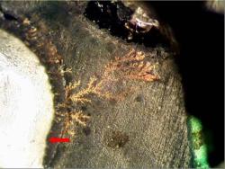
Gideon Analytical Laboratories received a PCB for failure analysis. The board was identified as having a short from the NET trace to the ground. The short measured about 10 ohms. One area of the board was abraded to reduce the thickness of the black solder mask. The board was received like this and we tried to change the refractive index to optically see through the solder mask. This was unsuccessful. The abraded area produces different optical characteristics, which prevent clear optical vision. Radiography did not work at all because the beam intensity attenuates and washes out any slivers traces that maybe there and works in principle by a density difference from the surrounding materials. Acoustic (sound waves, CSAM) microscopy did not work because either there are too many interfaces or the sliver may be too fine or the location is known in the material’s matrix.